Getting WiFi 7 Placement Right From the Start
WiFi 7 access points deliver impressive performance specifications—up to 46 Gbps theoretical throughput, multi-link operation, and 320 MHz channels on 6GHz. However, these capabilities mean little if access points are positioned incorrectly. A poorly placed WiFi 7 AP performs worse than a well-positioned WiFi 6 AP, regardless of the newer technology’s advantages.
Business network deployments reveal consistent patterns in placement mistakes. Access points mounted in equipment closets, positioned too close together, or placed without considering building materials create coverage gaps, interference issues, and performance problems that frustrate users and waste infrastructure investment.
Proper placement requires understanding radio frequency behavior, building construction, usage patterns, and interference sources. This guide examines common placement mistakes and provides practical strategies for optimal WiFi 7 access point positioning in business environments.
Understanding WiFi 7 Radio Characteristics
WiFi 7 introduces technical changes that affect placement decisions differently than previous WiFi generations. The 6GHz band provides clean spectrum but has reduced range compared to 2.4GHz and 5GHz. Multi-link operation allows simultaneous connections across bands, but only when clients can reach multiple radios effectively.
The 6GHz band’s shorter wavelength means it penetrates walls and obstacles less effectively than lower frequencies. A WiFi 6 access point might provide adequate coverage through two interior walls, while a WiFi 7 AP relying heavily on 6GHz may require line-of-sight or single-wall penetration for optimal performance.
320 MHz channel widths on 6GHz deliver maximum throughput but require strong signal strength to maintain connection stability. Clients at the edge of coverage areas typically fall back to narrower channels, reducing the practical benefit of WiFi 7’s wider channels. This behavior makes placement even more critical—access points must be positioned to maintain strong signals throughout coverage areas rather than barely reaching target zones.
When selecting between UniFi and Omada WiFi 7 platforms, placement principles remain consistent regardless of vendor. Both platforms benefit from proper AP positioning and suffer from the same placement mistakes.
Common Placement Mistakes and Their Consequences
Mounting Access Points in Equipment Closets
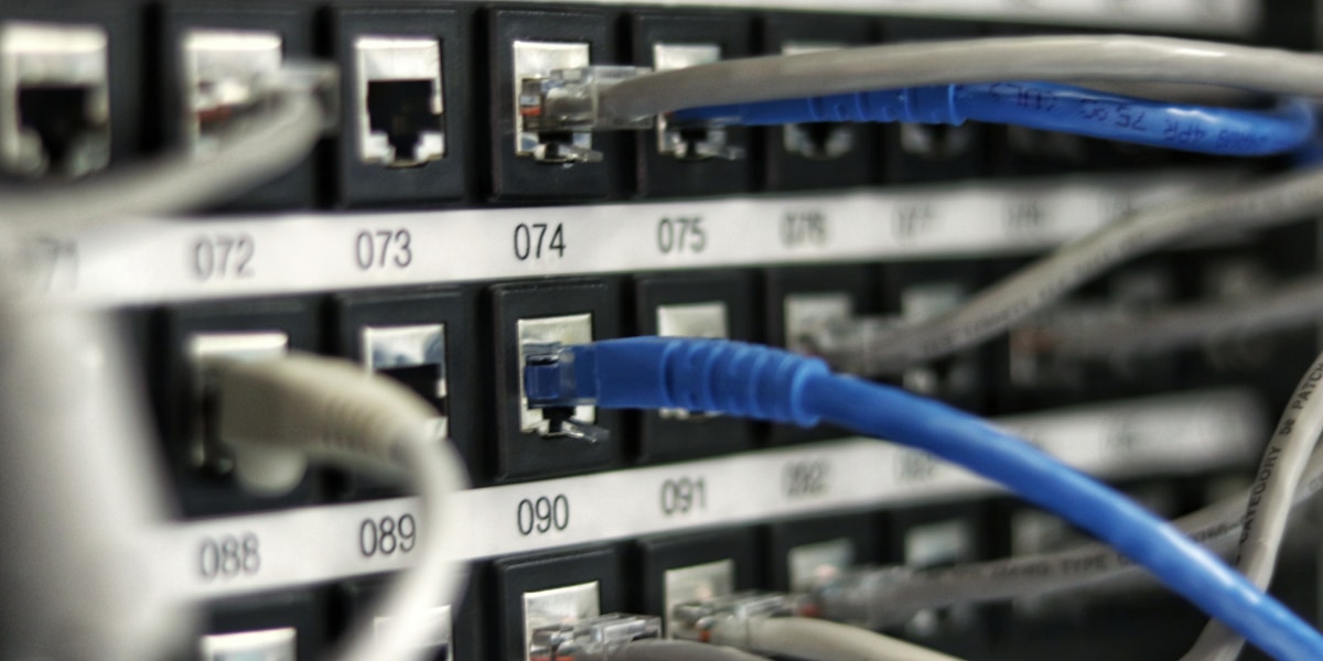
The most frequent placement error involves mounting access points in network equipment closets or IT rooms. This approach seems logical—power and network infrastructure are readily available, and the AP stays secure and out of sight. However, equipment closets are typically interior rooms surrounded by walls, often containing metal racks and equipment that block radio signals.
An access point mounted in an equipment closet must transmit through multiple walls to reach users. Each wall reduces signal strength by 3-15 dB depending on construction materials. Metal studs, concrete, or brick construction can reduce signals by 20-30 dB or more. The result is weak coverage throughout the office, forcing clients to connect at lower data rates or experience frequent disconnections.
Proper placement positions access points in or near the areas requiring coverage, not in the equipment closet. Use PoE to deliver power over network cables, eliminating the need for local power outlets and allowing flexible placement.
Positioning APs Too Close Together
Businesses sometimes install multiple access points in close proximity, assuming more APs automatically improve coverage. However, access points positioned too close create co-channel interference where their signals overlap and interfere with each other.
WiFi is a shared medium—only one device can transmit on a channel at a time within a coverage area. When multiple APs use the same channel in overlapping coverage zones, they compete for airtime, reducing overall network capacity. Clients caught between two strong signals may experience frequent roaming between APs, causing brief connection interruptions.
Optimal AP spacing depends on several factors including building construction, desired coverage area, and expected client density. General guidelines suggest 50-75 feet between APs in typical office environments, but site-specific factors may require closer or wider spacing.
Ignoring Building Materials and Construction
Different building materials affect WiFi signals dramatically. Drywall over wood studs provides minimal signal attenuation. Concrete, brick, metal studs, and low-E glass windows significantly reduce signal strength. According to NIST research on electromagnetic signal attenuation, concrete walls produce the greatest signal loss among common building materials. Ignoring these factors during planning leads to unexpected dead zones and coverage gaps.
A common scenario involves placing an AP in a hallway expecting it to cover adjacent offices. If those offices have concrete walls, the AP’s signal barely penetrates, leaving offices with weak or no coverage. Understanding construction materials before finalizing placement prevents these issues.
Request building plans showing wall construction types during the planning phase. If plans aren’t available, physical inspection reveals construction methods. Concrete walls, metal studs, and brick construction require more access points or different placement strategies than wood-frame construction with drywall.
Ceiling Height and Mounting Position Errors
Standard ceiling-mounted APs work well in typical office environments with 8-10 foot ceilings. However, businesses with high ceilings, dropped ceilings, or unusual architectural features require adjusted placement strategies.
High ceilings (15+ feet) increase the distance between APs and clients, reducing signal strength. The inverse square law means doubling the distance reduces signal strength by 6 dB. An AP mounted at 20 feet provides significantly weaker signal to floor-level clients than the same AP at 10 feet.
Dropped ceilings with metal framework can create unexpected interference. The metal grid acts as a partial Faraday cage, affecting signal propagation in unpredictable ways. Testing signal strength in actual deployment conditions reveals these issues before full installation.
Strategic Placement Guidelines
Effective WiFi 7 placement follows systematic principles that account for building characteristics, usage patterns, and technical requirements.
Coverage Area Planning
Key placement principles:
- Start with a floor plan - Mark walls, construction materials, and obstacles
- Identify high-usage areas - Conference rooms, workstations, common areas require priority coverage
- Consider client density - Areas with many simultaneous users need more capacity
- Account for vertical coverage - Multi-story buildings require APs on each floor
- Plan for outdoor areas - Loading docks, patios, and parking areas may need coverage
- Include future expansion zones - Plan capacity for areas that may add users later
Optimal Mounting Locations
Access points perform best when mounted in open areas with minimal obstructions between the AP and clients. Hallways, common areas, and open office spaces provide better mounting locations than enclosed rooms.
Wall-mounted APs work well in specific scenarios. Conference rooms benefit from wall-mounted units that provide focused coverage within the room. Long corridors may use wall-mounted APs at intervals rather than ceiling-mounted units. The UniFi U7 Pro Wall specifically addresses wall-mounting scenarios with directional antenna patterns.
Avoid mounting APs near metal objects, HVAC equipment, or other potential interference sources. Metal filing cabinets, server racks, and large appliances can block or reflect signals, creating dead zones or unexpected coverage patterns.
Interference Management
WiFi 7 operates on three bands—2.4GHz, 5GHz, and 6GHz. Each band has different characteristics and interference considerations.
The 2.4GHz band suffers from congestion in most business environments. Neighboring businesses, Bluetooth devices, microwave ovens, and wireless cameras all compete for the limited 2.4GHz spectrum. While WiFi 7 still supports 2.4GHz for backward compatibility, avoid relying on it for primary connectivity.
The 5GHz band provides more channels and less interference than 2.4GHz, but faces congestion in dense office buildings where multiple businesses operate WiFi networks. Proper channel selection and power level adjustment minimize interference between neighboring networks.
The 6GHz band offers clean spectrum with minimal interference in most environments. However, 6GHz’s shorter range means access points must be positioned closer to clients for effective coverage. This trade-off between clean spectrum and reduced range affects placement density.
Site Survey and Validation Process
Theoretical planning provides a starting point, but physical site surveys validate placement decisions before full deployment. Professional network design approaches include pre-deployment surveys and post-deployment validation.
Pre-Deployment Survey Steps
- Physical walkthrough - Document building layout, construction materials, and obstacles
- Interference analysis - Identify existing WiFi networks and interference sources using spectrum analyzer tools
- Preliminary AP placement - Mark proposed locations on floor plans
- Coverage modeling - Use planning software to estimate coverage patterns
- Adjust for obstacles - Modify placement based on construction materials and physical barriers
Post-Deployment Validation
After installing access points, validation testing confirms actual coverage matches planning expectations. Walk the facility with a WiFi analyzer measuring signal strength, data rates, and interference levels throughout coverage areas.
Target signal strength of -67 dBm or stronger throughout primary coverage areas ensures reliable connectivity. Areas with weaker signals may experience reduced data rates or connection stability issues. Dead zones with signals below -70 dBm typically require additional access points or repositioning existing units.
Comparing Placement Requirements Across Scenarios
Different business environments require adjusted placement strategies based on usage patterns and physical characteristics.
| Environment Type | Typical AP Spacing | Key Considerations | Mounting Preference |
|---|---|---|---|
| Open Office | 50-75 feet | High client density, minimal obstacles | Ceiling-mounted, central positioning |
| Private Offices | 30-50 feet | Wall penetration, individual room coverage | Hallway ceiling mounts or in-room wall mounts |
| Warehouse | 75-100 feet | High ceilings, metal shelving, minimal clients | High-power ceiling mounts, directional antennas |
| Retail Floor | 40-60 feet | Customer density, point-of-sale requirements | Ceiling-mounted, focused on transaction areas |
| Conference Rooms | One AP per room | High simultaneous client count, video conferencing | Wall-mounted or dedicated ceiling mount |
| Outdoor Areas | 100-150 feet | Weather exposure, line-of-sight coverage | Weather-rated outdoor APs, elevated mounting |
These guidelines provide starting points, but site-specific factors may require adjustments. A warehouse with extensive metal shelving needs closer AP spacing than an empty warehouse. An office with concrete walls requires more APs than the same layout with drywall construction.
Professional Assessment Value
While general guidelines inform placement decisions, professional site surveys account for variables that generic recommendations can’t address. Building-specific construction, local interference sources, and unique usage patterns affect optimal placement in ways that require on-site assessment.
Professional network installers bring experience from hundreds of deployments, recognizing patterns and potential issues that aren’t obvious from floor plans alone. They use specialized tools to measure signal strength, identify interference sources, and validate coverage before finalizing installation.
The cost of professional assessment typically represents 10-15% of total installation cost but can prevent expensive mistakes that require relocating access points after installation. Relocating ceiling-mounted APs involves additional cabling, patching, and labor that often exceeds the original assessment cost.
Practical Next Steps
Effective WiFi 7 deployment starts with proper planning and continues through validation and optimization. Begin with accurate floor plans and building construction information. Identify high-priority coverage areas and expected client density. Consider future expansion needs that may affect placement decisions.
For businesses evaluating WiFi 7 platforms, the UniFi vs Omada comparison examines hardware options and ecosystem considerations. However, platform selection matters less than proper placement—both systems perform well when positioned correctly and poorly when placed incorrectly.
Test coverage after initial installation using WiFi analyzer tools or professional survey equipment. Validate that signal strength meets targets throughout coverage areas. Adjust AP positions or add units to address gaps discovered during testing.
Key Takeaway: WiFi 7’s advanced capabilities deliver value only when access points are positioned to provide strong, consistent signals throughout coverage areas. Proper placement planning prevents common mistakes that undermine network performance regardless of hardware quality.
Need expert guidance on WiFi 7 network design and deployment? Learn more about our network planning approach or contact iFeeltech for professional site assessment and installation services.